Published
- 19 min read
Building a home alarm with an ESP32 and a testable state machine
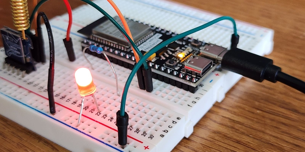
I built a home alarm called galitas32. It runs on an ESP32-S3 board with a camera, reads a reed switch on the door, flashes a LED strip, screams through a buzzer, is armed and disarmed with an RFID card and talks to me via Telegram.
The hardware is the easy part: a handful of cheap modules and some wires. This post is about the design decisions that made the software something I trust to guard my front door: the state machine, the hardware abstraction layer and the rules about what is allowed to block what. The code is on GitHub.
The requirement that shaped everything
The first line of my requirements says it all:
The physical mechanisms must work regardless of the network connection. When the network is enabled, it will act as an enhancement.
An alarm that stops working when the router reboots is useless. So Wi-Fi and Telegram are optional extras and the door sensor, the LED, the buzzer and the RFID reader must work with the network cable pulled. This single rule drives most of the decisions below.
The state machine
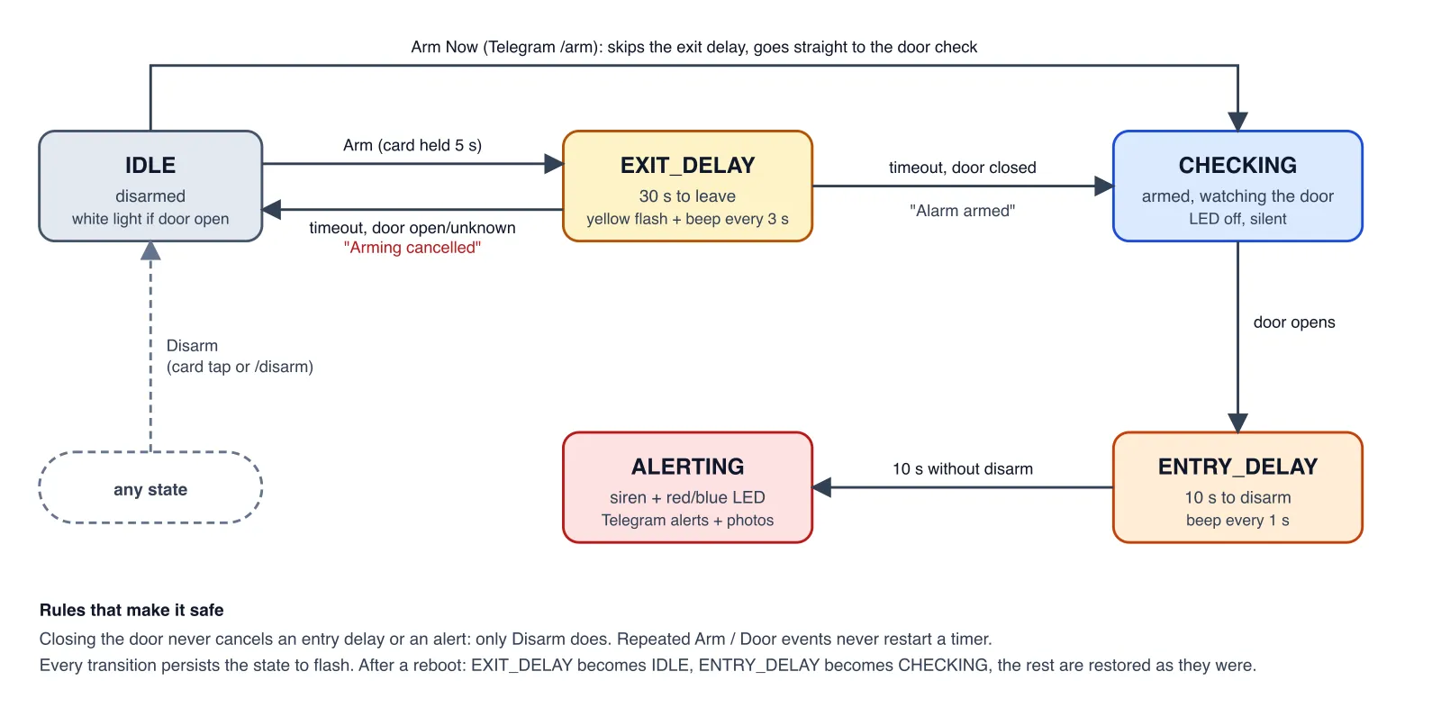
A few booleans (armed, doorOpen, alerting…) fall apart the moment you ask “what happens if I arm it while the door is open?”. So I describe the behaviour as an explicit state machine, in a Markdown document that lives in the repo and acts as the specification the tests are written against.
There are five states:
| State | Meaning |
|---|---|
IDLE | Disarmed. A white light turns on when the door is open. |
EXIT_DELAY | I asked to arm, I have 30 seconds to leave and close the door. |
CHECKING | Armed. Silently watching the door. |
ENTRY_DELAY | The door opened while armed, 10 seconds to disarm. |
ALERTING | Intrusion. Siren, lights, Telegram alerts, photos. |
The state is just an enum:
enum class AlarmState : uint8_t
{
    Idle = 0,
    ExitDelay = 1,
    Checking = 2,
    EntryDelay = 3,
    Alerting = 4
};
Having exit and entry delays as states instead of timers hanging off a boolean is what makes the rest tractable: each state has clear entry actions, clear exit actions and a closed list of events it reacts to.
Events, not readings
The state machine only knows five events: door opened, door closed, arm, arm now and disarm. It never sees a raw sensor reading and it does not know whether a command came from the RFID card or from Telegram. That is enforced by two tiny observer interfaces:
class DoorObserver
{
public:
    virtual void onDoorStateChanged(DoorState state, uint32_t now) = 0;
};

class ArmDisarmObserver
{
public:
    virtual void arm(uint32_t now) = 0;
    virtual void armNow(uint32_t now) = 0;
    virtual void disarm(uint32_t now) = 0;
};
Alarm implements both. Something has to turn the raw, noisy hardware into those clean events: for the door that is a debouncer, described in Debouncing the door.
Decisions I took (and why)
Writing the transition tables forced me to take decisions I would have otherwise taken accidentally, in the middle of the code. These are my favourites:
Closing the door does not cancel an intrusion. Once the door opens, the entry delay is running, and shutting the door again doesn’t stop it: if nobody disarms within 10 seconds, the siren and the lights are triggered anyway. Only disarm can stop it. If closing the door were enough, an intruder could simply open it, step back and close it again to silence the alarm.
Repeated events never restart timers. Pressing arm twice, or the door bouncing open/closed during the exit delay, does not give an intruder (or me) extra time. transitionTo just ignores a transition to the current state:
void transitionTo(AlarmState next, uint32_t now)
{
    // Repeated commands never restart timers or entry actions.
    if (next == state_)
        return;
    ...
}
The system does not wait forever for the door to close. If I arm and the door is still open after 30 seconds, arming is cancelled, I get a distinctive beep pattern and a Telegram message. Silently staying in EXIT_DELAY forever, or worse, arming with an open door, are both worse.
The door can be UNKNOWN. The door has three states, not two: Open, Closed and Unknown (no valid reading yet). I refuse to assume the door is closed, so arming with an unknown door fails the same way as arming with an open one.
Two ways to arm. The RFID card arms with an exit delay because I’m about to walk out. The Telegram /arm command is “Arm Now”: it skips the exit delay and checks the door immediately, because if I’m using the phone it’s because I forgot to arm it and I’m already away.
Disarming works from any state, even CHECKING with the door closed. And it always wins: if the entry timeout and a disarm are processed in the same loop iteration, you end up in IDLE.
Surviving a reboot
An alarm that forgets it was armed when the power blinks is a bad alarm. Every transition persists the state to the ESP32 flash (NVS, behind an AlarmStateStorage interface). Timers are not persisted, so recovery has to decide what a restart means for each state:
| Saved state | Restored state | Why |
|---|---|---|
IDLE | IDLE | |
EXIT_DELAY | IDLE | Arming was interrupted: cancel it and tell me. |
CHECKING | CHECKING | Still armed. |
ENTRY_DELAY | CHECKING | The interrupted entry delay is discarded. If the door is still open, a fresh one starts. |
ALERTING | ALERTING | Resume the siren immediately, without waiting for a door reading. |
The whole policy is a 30-line pure function that is trivially testable:
if (saved == AlarmState::ExitDelay)
{
    result.state = AlarmState::Idle;
    result.armingCancelled = true;
}
else if (saved == AlarmState::EntryDelay)
{
    result.state = AlarmState::Checking;
}
The interesting one is ENTRY_DELAY → CHECKING. Is it a hole? Cutting the power during the entry delay resets the 10 seconds, but the door is still open on boot, so a new entry delay starts right away. An intruder gains 10 seconds, nothing else.
Hardware abstraction layer
Here is the question that changed the project: how do I test a state machine that talks to a buzzer, a LED strip and an RFID reader?
Flashing the board for every change gets old very fast, especially when the scenario I want to test is “arm, wait 30 seconds, open the door, wait 10 seconds”. The answer is the classic one: the logic must not know the hardware exists.
The project is split in two:
lib/AlarmCore: the state machine, the controllers and all the interfaces. Pure C++, there is not a single#include <Arduino.h>in it.src/: the ESP32-only code: the adapters that implement those interfaces with real hardware, plus the Telegram integration and the wiring inmain.cpp.
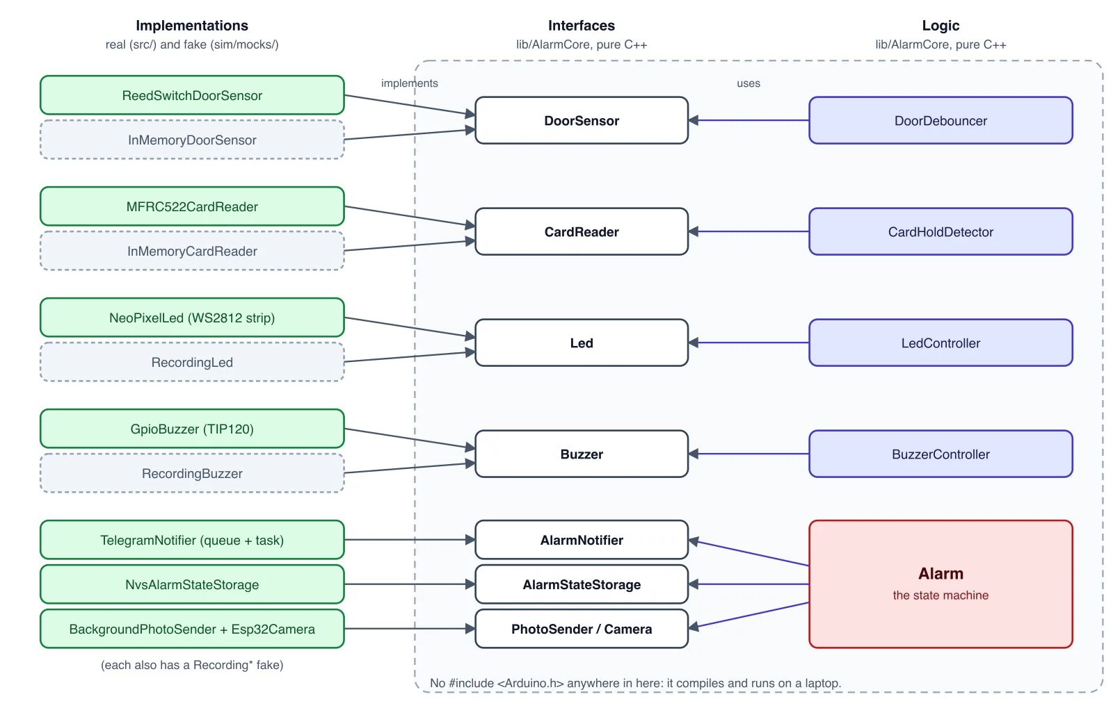
Every device is reduced to the smallest interface the logic needs. For example, the door sensor:
enum class DoorState { Unknown, Closed, Open };

class DoorSensor
{
public:
    virtual ~DoorSensor() = default;
    virtual DoorState read() const = 0;
};
And the real implementation is the only place that knows about pins, pull-ups and polarity:
DoorState read() const override
{
    return digitalRead(pin_) == LOW
               ? DoorState::Closed
               : DoorState::Open;
}
The buzzer is one method (setEnabled(bool)), the LED strip is another (setColor(LedColor)), the camera is takePicture / releasePicture… Keeping them this dumb has a nice side effect: swapping the WS2812 strip for another thing, or the RFID module, only touches one small adapter.
Dependency injection by hand
No framework, no singletons. Everything is wired in the constructor, and main.cpp is the only place where concrete types are named:
// board hardware
NeoPixelLed led(LED_PIN, LED_COUNT);
MFRC522CardReader cardReader(RFID_PINS);
ReedSwitchDoorSensor doorSensor(DOOR_SENSOR_PIN);
GpioBuzzer buzzer(BUZZER_PIN);

// actuators
LedController ledController(led, {});
BuzzerController buzzerController(buzzer, {});

// state machine
Alarm galitasAlarm(ledController, buzzerController, telegramNotifier,
                   nvsStorage, photoSender, {});

// input processors
CardHoldDetector cardHoldDetector(galitasAlarm, cardReader);
DoorDebouncer doorDebouncer(galitasAlarm, doorSensor);
Two layers between the state machine and the hardware
The state machine does not tell the LED “be red”. It says “I’m alerting”. Between the two there are two thin layers:
AlarmSignalstranslates alarm events (enter(state),leave(state),disarmed(),warning()…) into calls to the LED and buzzer controllers.Alarmonly ever talks toAlarmSignals.LedControllerandBuzzerControllerown how things look and sound: beep patterns, the 250 ms red/blue alternation, the yellow flash. They only talk to the dumbLed/Buzzerinterfaces.
Several things can ask for the same LED at the same time (the door is open and I just disarmed and an exit countdown is running), so each controller has a priority list and picks the strongest active signal on every update:
| Priority | LED | Buzzer |
|---|---|---|
| 1 (highest) | red/blue blinking (alerting) | continuous siren |
| 2 | green for 10 s (disarm confirmation) | confirmation beeps (armed, disarmed, warning) |
| 3 | yellow flash (exit countdown) | countdown beeps |
| 4 | white (door open) | silence |
| 5 | off |
When a higher-priority signal ends, the controller naturally falls back to whatever is next. There is no “restore previous colour” code to get wrong. It also gives me the rule that closing the door never kills the green disarm confirmation, for free.
Cooperative scheduling and a clock that is a parameter
The firmware has no RTOS tasks for the core logic. loop() is a plain sequence, and it is the only thing that moves the state machine forward:
void loop()
{
    const unsigned long now = millis();

    doorDebouncer.update(now);
    cardHoldDetector.update(now);
    telegramCommandsReceiver.processTelegramCommands(now);

    galitasAlarm.update(now);

    ledController.update(now);
    buzzerController.update(now);

    delay(1);
}
Notice that millis() is read once and passed down as now to everyone. No class in the core calls a clock itself. That has three nice consequences:
- Every component sees a consistent instant within one iteration.
- Tests control time. “Wait 30 seconds” is
alarm.update(30100), not a 30 second sleep. - Rollover is handled in one place.
millis()wraps every ~49 days, and an alarm should survive that. All durations use unsigned subtraction:
inline bool hasElapsed(uint32_t now, uint32_t startedAt, uint32_t duration)
{
    return static_cast<uint32_t>(now - startedAt) >= duration;
}
Input processors: turn noise into events
Two small classes sit between hardware and the state machine and are where the “physical world” gets cleaned up.
Debouncing the door
A reed switch is a mechanical contact. When the magnet moves away (or slams back because the door was closed hard), the contact doesn’t change cleanly from closed to open: it chatters for a few milliseconds, and a vibrating door frame can add more noise on top. The microcontroller polls the pin thousands of times per second, so it would happily see open, closed, open, open, closed... for a single physical event.
If those readings went straight into the state machine, one door slam could produce a burst of “door opened” / “door closed” events, and with them a burst of Telegram messages and spurious transitions. So DoorDebouncer sits between the sensor and the Alarm. It only reports a change once the new reading has been stable for 50 ms:
void update(uint32_t now)
{
    const DoorState reading = sensor_.read();

    // Every time the reading changes, we reset the candidate and the timer.
    if (reading != candidate_)
    {
        candidate_ = reading;
        candidateSince_ = now;
    }

    // only accept a different state if it has been stable for the debounce period
    if (candidate_ != stable_ &&
        static_cast<uint32_t>(now - candidateSince_) >= debounceMs_)
    {
        stable_ = candidate_;
        observer_.onDoorStateChanged(state(), now);
    }
}
There are no delay() calls and no interrupts: the debouncer just remembers a candidate reading and when it first appeared, and is polled from loop() like everything else. The state machine then only ever sees confirmed changes, and Alarm ignores a notification that repeats the state it already has. Because it is a plain class that reads a DoorSensor and takes the time as a parameter, it is unit tested with a fake sensor that flips values at chosen instants.
Tap or hold the card
CardHoldDetector turns “the RFID reader sees a card” into a gesture:
- Tap the card (release before 5 seconds): disarm.
- Hold the card for 5 seconds: arm, emitted once, while the card is still on the reader.
Why hold to arm? Because disarming should be effortless when you walk in and the siren is about to start, while arming should be deliberate. It also means a card lying close to the reader can’t re-arm the alarm by accident. The detector tolerates small gaps in reads (250 ms), because the RFID module misses reads from time to time, and ignores cards that are not in the allow list.
Telegram must never block the siren
Telegram is the part that is allowed to be slow, flaky and sometimes absent. The rule is simple: nothing in the alarm may wait for the network.
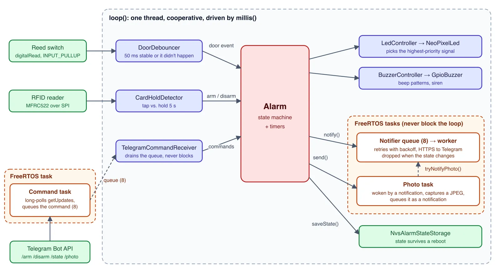
An HTTPS request to Telegram can take seconds, and a photo upload even more. Doing that from loop() would freeze the siren and the door debouncing. So the network work lives in FreeRTOS tasks and talks to the main loop through queues:
- Outgoing messages.
AlarmNotifier::notify()copies the text into a queue (capacity 8) and returns immediately. A worker task delivers it, retrying with backoff. The interface documents the contract: “Must not wait for the network.” - Incoming commands. A second task long-polls Telegram’s
getUpdatesand pushes each command it recognises into another queue. It never touches the alarm. The consuming side isTelegramCommandReceiver, which runs insideloop(): on every iteration it drains that queue without blocking and translates each command into a call on the alarm (armNow(),disarm(), and so on). The state machine is therefore only ever driven from the main loop, so the core needs no locks. - Photos. Taking a JPEG is slow, so
BackgroundPhotoSender::send()only doesxTaskNotifyGive()on a photo task and returns. If several requests arrive while a capture is running, they are coalesced into one.
Two more details I like:
Stale notifications are dropped. Telegram being slow can leave messages in the queue. Delivering “Door opened” after I’ve already disarmed would be confusing. So every state change calls cancelPendingNotifications(), which drains the queue and aborts any retrying delivery (a generation counter makes the in-flight retry give up). Messages describe the state they were sent from, or they don’t get sent.
A watchdog for connectivity. If Telegram doesn’t answer at all for 2 minutes, the firmware re-associates the Wi-Fi. After 10 minutes, it reboots. That is safe precisely because the state is persisted and recovered as described above: a reboot in ALERTING resumes the siren immediately.
What an intrusion looks like
Putting it all together, this is the timeline of the happy path: I arm, the house is quiet for a while, someone opens the door and nobody disarms.
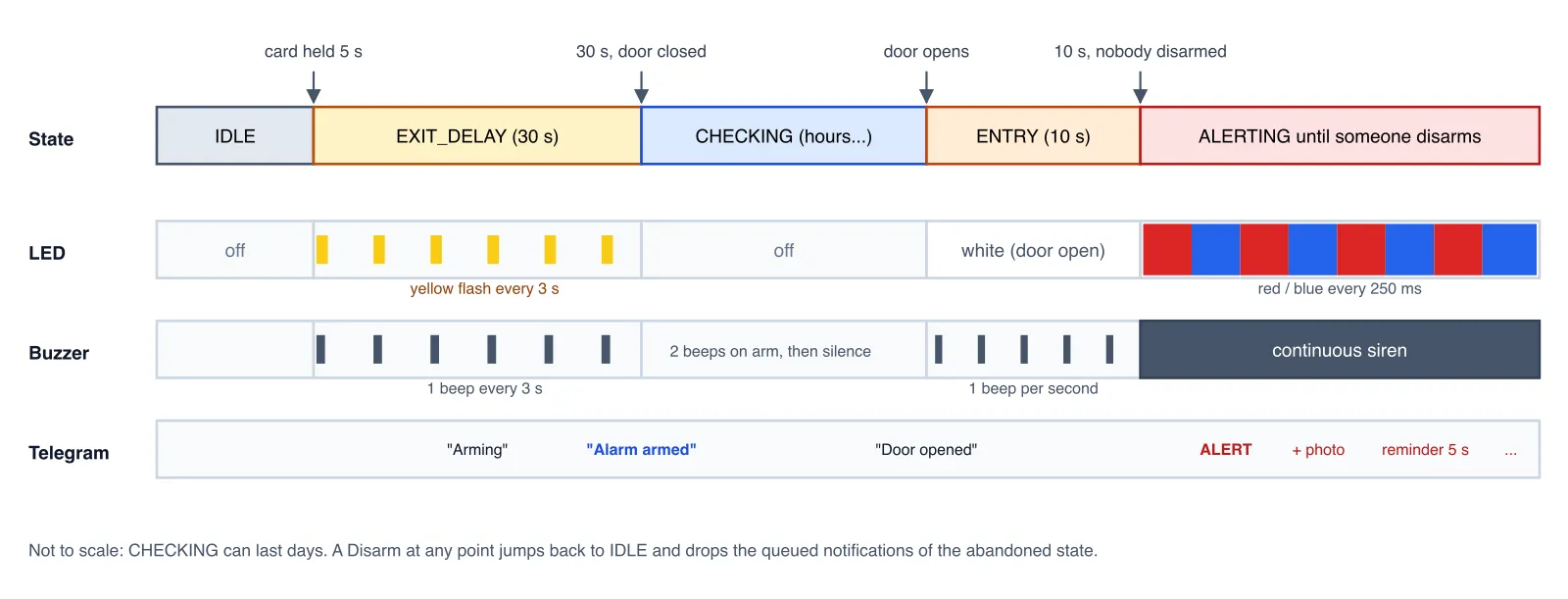
While alerting, reminders are sent every 5 seconds and a photo is requested every 5 seconds too, so I get a stream of pictures of whoever is in the hallway. The local siren does not depend on any of that arriving.
Testing without a board
Because the core is pure C++ and takes the clock as a parameter, the whole state machine runs natively on my laptop. PlatformIO lets you define several build environments in platformio.ini, each with its own platform, source filter and flags, so I defined three:
| Environment | What it does |
|---|---|
esp32s3 | The real firmware for the board. |
native | Builds lib/AlarmCore for the host and runs the Unity tests. |
sim | A small terminal program that wires the real Alarm to fake hardware, so I can press keys to open the door, tap a card and watch the LED and buzzer logs. |
For every interface there is a fake in sim/mocks/ that records what happened. The buzzer fake, for instance, is just:
class RecordingBuzzer : public Buzzer
{
public:
    void setup() override {}
    void setEnabled(bool enabled) override
    {
        enabled_ = enabled;
        ++writeCount_;
    }

    bool enabled_ = false;
    unsigned writeCount_ = 0;
};
A test then reads like the specification. This one checks that the exit delay arms exactly at the deadline when the door is closed, and not one millisecond before:
void test_exit_delay_arms_at_exact_deadline_when_door_is_closed()
{
    Fixture f;
    f.begin();

    f.alarm.onDoorStateChanged(DoorState::Closed, 0);
    f.alarm.arm(100);

    f.alarm.update(30099);
    assertState(State::ExitDelay, f.alarm);

    f.alarm.update(30100);
    assertState(State::Checking, f.alarm);

    TEST_ASSERT_EQUAL_UINT32(1, f.notifier.count("Alarm armed"));
    TEST_ASSERT_TRUE(f.stateStorage.savedState == State::Checking);
}
There are over 120 of them: exit and entry delays, recovery after reboot for every state, millis() rollover, the card gestures, LED and buzzer priorities… Native line coverage of the core is about 98%. CI runs the tests, the coverage report and static analysis (clang-tidy) on every push, and also compiles both the simulator and the real firmware, so a change that breaks the board build is caught even if the tests pass.
The time I save is real. The scenarios that matter for an alarm (what happens at second 29.9? what if the power dies during the entry delay? what if I disarm at the same millisecond the alert starts?) are exactly the ones I would never test by hand.
Hardware, briefly
Since the post is about software I only sketch the hardware. The board is an ESP32-S3 with camera. It’s wired like this:
- Door: a reed switch between a GPIO and GND, using
INPUT_PULLUP. A closed contact readsLOW. The downside, which I documented as an explicit limitation, is that an open door and a cut wire look the same. Both are treated as an open door, which is the safe failure mode for an alarm. - LED strip: WS2812 on one data pin through a 330 Ω resistor, powered by an external 5 V supply with a common ground.
- Buzzer: driven through a TIP120 transistor (the GPIO can’t power it directly) with a 1 kΩ resistor on the base.
- RFID: an MFRC522 over SPI.
The case: 3D design with ChatGPT and OpenSCAD
A bare ESP32 board with a camera taped to a door frame is not something I want in my hallway, so the project needed a proper enclosure. I’m not a 3D designer, so I let ChatGPT do the modelling: instead of drawing in a CAD tool, I asked it to write OpenSCAD code. OpenSCAD describes solids with code (cubes, cylinders, unions, differences), which is a format a language model is quite good at, and a parametric one: every dimension is a variable I can tweak and re-render. Then I exported the STL files and printed them on my 3D printer.
Writing the brief
The result is only as good as the specification. I wrote a long brief (it’s in the repo as case/case.md) that read more like a requirements document than a prompt:
- Looks: it should look like a commercial wall-mounted detector, not a generic project box: vertical, rounded, around 190 × 74 × 44 mm, no visible screws or vents on the front and a clean surface with only the camera opening.
- Maintenance: the rear shell stays on the wall and the electronics live in it. The front shell comes off to open the alarm, so the only thing connecting both halves is the camera ribbon.
- Closing system: two hooks at the top, and two M3 screws at the bottom that thread into heat-set inserts. The hooks must physically overlap their catches: no decorative hooks.
- Printability: it has to print on a regular FDM printer without a mess of supports, with realistic tolerances for the inserts.
- Decisions are final: I wrote explicitly that already-taken decisions must not be reverted. Without that, a chat assistant tends to “improve” something you had already settled when you ask for an unrelated change.
An AI that has to prove its work
A language model writing geometry has no eyes. It can produce code that compiles, renders and is still wrong: a screw that goes through nothing, a hook that doesn’t reach its catch, a wall thinner than the nozzle. So the brief ended with “the goal is not to produce an STL that looks right, but one that can be assembled, disassembled, printed and verified”, and the repo contains the verification scripts that came out of that:
export_parts.pyrenders each part of the.scadfile to STL with OpenSCAD.verify_meshes.pyusestrimeshto check that every mesh is watertight, manifold, has no degenerate faces or stray components and fits in the printer bed.verify_structure.pychecks the assembly: the USB opening, the screw paths, whether the hooks really overlap their catches, and so on.
It’s the same philosophy as the rest of the project: don’t trust it because it looks right, make a machine check it.
Iterating
It was not one prompt. The history of the case/ folder in the repo is a list of rounds: a first version, fixes to the board bed sizing, and a redesign of the mounting. My original idea was an adjustable camera cradle with a pivot so I could aim it between 10° and 35° downward. In the end I simplified it: the camera stays on its board and the whole case is tilted 20° downward by its wall bracket, which hangs from a screw through a keyhole slot. The final .scad file is sized around my own door: the distance from the screw to the top of the door frame (measured) and the clearance the door needs when it opens. Some values, like how far the frame protrudes from the wall, are still marked as assumptions in the code.
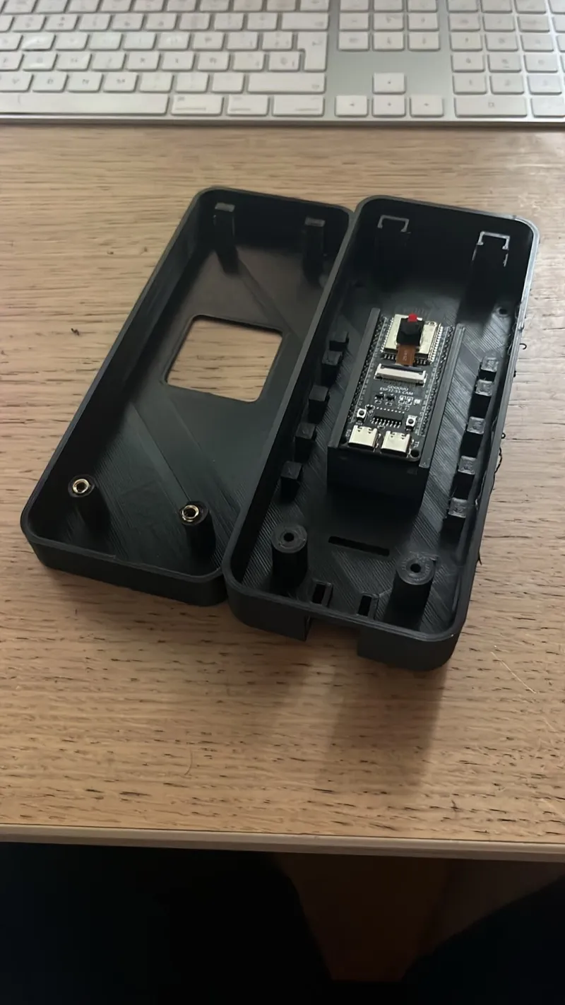
Here is the result, printed. The front shell on the left has the camera window and, in the two bosses at the bottom, the brass heat-set inserts that the M3 screws thread into. The rear shell on the right holds the ESP32-S3-CAM board in its rails, with the slots for the Dupont connectors along both sides and the catches for the hooks at the top:
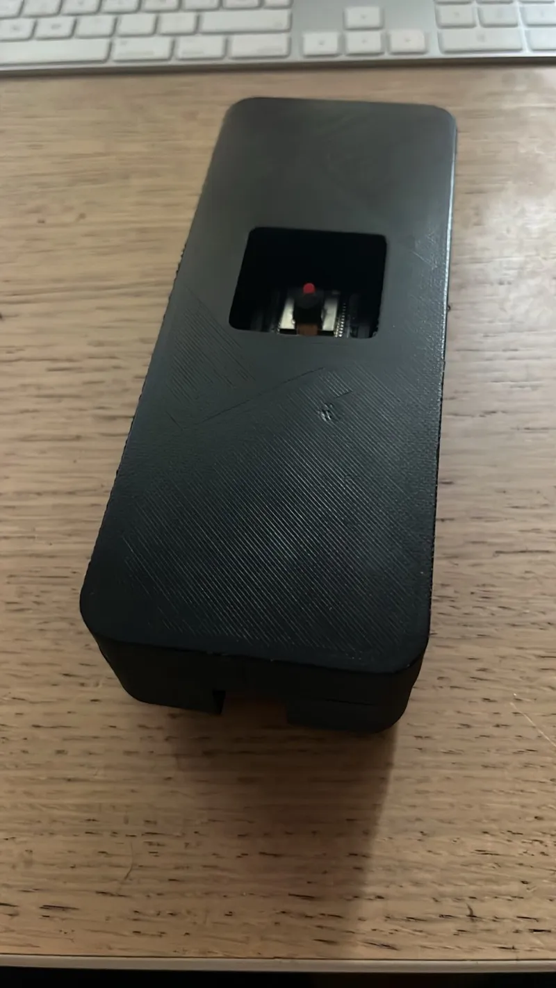
And closed, with the camera looking through the window. The diagonal marks on the surface are just the print’s infill pattern showing through the top layers; you only notice them if you look for them:
What I learned from designing with an AI
- Parameters beat prompts. Having
case_w,wall,wall_tilt,camera_window_w… as variables at the top of the file means changing the design is a one-line edit and a re-render, not a new conversation with the model. - Make it flag its assumptions. The code is full of comments like “ASSUMED protrusion from wall” or “estimated, check against the real board before printing”. Those comments are a to-do list of things to measure.
- Verify with tools, not with your eyes. Render, run the scripts and only then waste plastic on a print.
- Print the risky part first. The tolerances of heat-set inserts and hooks are what the digital model can’t tell you; a small test print can.
Lessons learned
- Write the state machine down. A table of states, events and transitions forces you to answer the awkward questions (arm with the door open? reboot mid-alert?) on paper instead of in production.
- A hardware abstraction layer is mostly about testing. I expected to swap a component someday, but what I actually got is the ability to run the alarm on a laptop with a fake clock.
- Inject time. Passing
nowaround costs nothing and makes timers, rollover and recovery testable. - Decide what is allowed to block what. Everything that can be slow (network, camera) lives behind a queue or a task notification, and everything safety-critical stays in a loop that never waits.
- Make failure modes explicit. Unknown door, cut wire, interrupted arming, reboot while alerting. The unhappy paths are what an alarm is for.
The things on my list are first-startup policy (currently it starts disarmed when there is no saved state) and cable supervision for the door sensor. The full source, the state machine document and the wiring diagrams are in the repository.